Use this free worm and worm gear cutting calculator to find the main values needed for milling machine setup. Enter the worm diameter, worm lead, and number of starts to calculate module, worm angle, worm gear angle, and whole depth.
Worm gear sets are commonly used where high reduction, smooth motion, and compact design are required. This page helps machinists, students, and engineers prepare the correct dimensions before cutting.
Tip: Check your values carefully before submitting. Accurate input gives more reliable machining results.
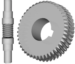
Worm and worm gears are widely used in machinery for power transmission, especially in applications requiring high torque reduction and smooth operation. Manufacturing these gears on a milling machine requires precision to ensure proper meshing and efficient performance.
The process begins with selecting the appropriate materials for the worm and worm gear. The worm is typically made from hardened steel or alloy steel for strength, while the worm gear is often made from phosphor bronze or brass to reduce friction and wear. The gear blank is prepared with the correct diameter and thickness based on design specifications. The lead angle, module, number of teeth, and pressure angle are crucial parameters that must be determined before machining.
A universal milling machine equipped with a dividing head and lead screw attachment is used for cutting the worm and worm gear. The worm is machined using a thread milling cutter, ensuring precise helical thread formation. For the worm gear, a specially designed form cutter or hob is used to generate accurate gear teeth. The dividing head is set to match the required gear ratio, ensuring the correct profile and alignment.
After cutting, the worm and worm gear undergo finishing processes such as deburring, heat treatment, and grinding to enhance durability and precision. This method ensures high-quality worm gear sets suitable for industrial applications, including conveyors, lifts, and machine tools.