 Engineer
Introduction
Worm gears are one of the most versatile and powerful mechanical power transmission components in engineering. They enable high reduction ratios in a compact space, provide smooth and quiet operation, and offer the unique ability to achieve self-locking — making them indispensable in applications ranging from conveyor systems and elevators to automotive steering and industrial machinery.
This comprehensive guide covers every aspect of worm gear engineering — from basic definitions and design formulas to manufacturing processes, practical workshop tips, and real-world applications. Whether you're a student learning the fundamentals or an experienced engineer designing a power transmission system, you'll find actionable, technically accurate information here.
 What is a Worm Gear?
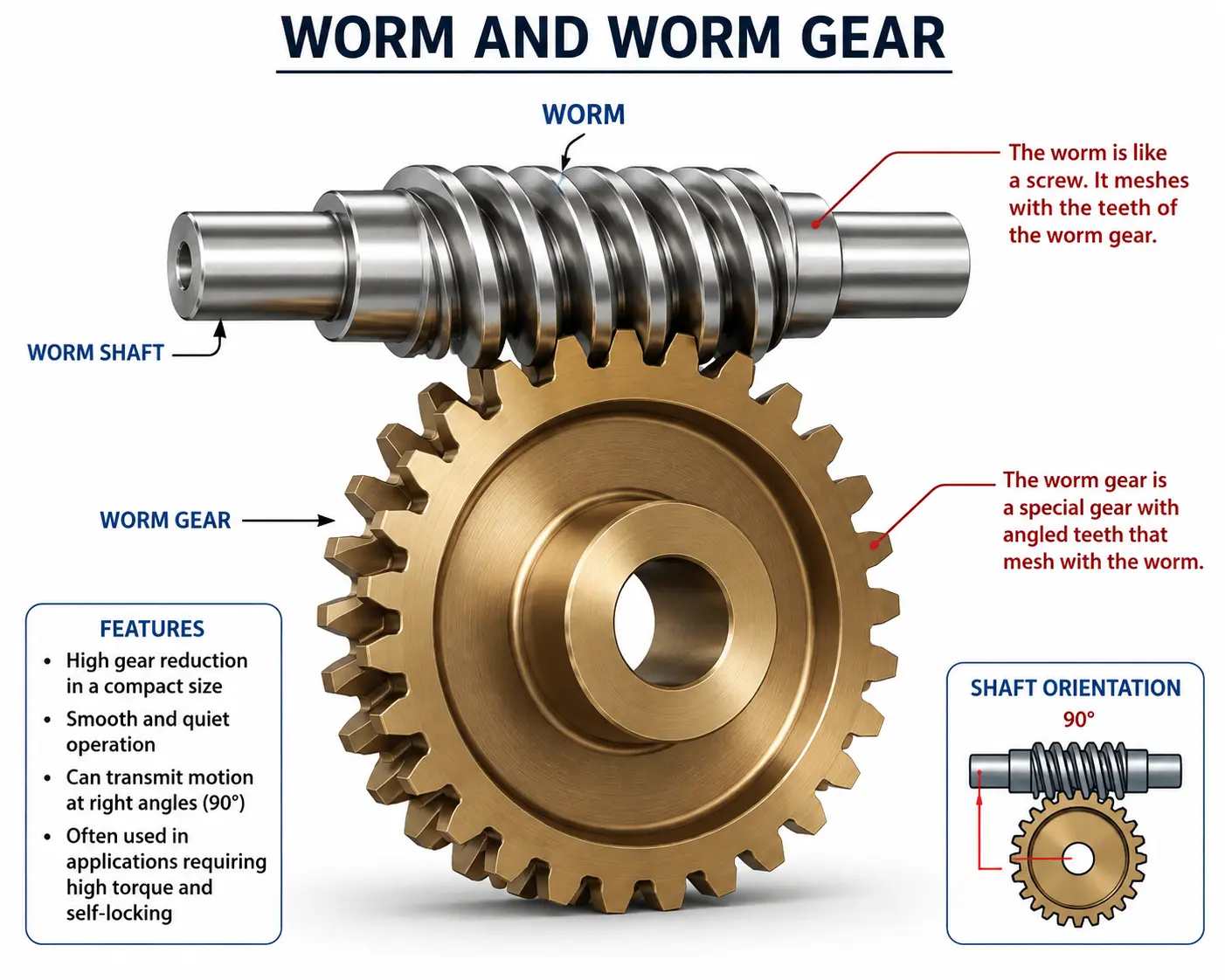
What is a Worm Gear?A worm gear is a power transmission system consisting of a worm (a threaded shaft resembling a screw) and a worm wheel (a gear with specially cut teeth that mesh with the worm). The worm resembles a screw with helical threads, and the worm wheel is a gear with teeth cut at an angle to match the worm's helix.
The worm gear is one of the oldest gear types, with origins dating back to ancient times. The concept of using a screw to drive a gear was first documented by Archimedes, and the modern worm gear was developed during the Industrial Revolution for heavy machinery applications.
Key characteristics:
- High reduction ratios (from 5:1 up to 100:1 or more in a single stage).
- Compact design — large reductions in a small footprint.
- Smooth and quiet operation due to gradual tooth engagement.
- Self-locking capability (the worm can drive the wheel, but the wheel cannot drive the worm).
- High shock load resistance.
Why is Worm Gear Design Important?
Proper worm gear design is critical for several reasons:
- Power transmission efficiency: Worm gears typically have lower efficiency (40–85%) compared to other gear types, so optimizing design is essential to minimize energy loss.
- Reliability and durability: Worm gears must withstand high sliding velocities and contact stresses without premature wear or failure.
- Self-locking behavior: In applications like hoists and elevators, self-locking is a safety-critical feature that must be carefully designed.
- Heat generation: The sliding action generates significant heat, requiring proper lubrication and thermal management.
- Cost: Optimized designs reduce material waste and manufacturing costs.
By understanding the engineering principles behind worm gears, you can design reliable, efficient, and cost-effective power transmission systems that meet the specific demands of your application.
Types of Worm Gears
Worm gears are classified based on the geometry of the worm and the worm wheel. The main types are:
| Type | Description | Common Use |
|---|---|---|
| Single-Start Worm | One helical thread on the worm | High reduction ratios (self-locking) |
| Multi-Start Worm | Two or more threads (double, triple, etc.) | Higher efficiency, lower reduction |
| Straight-Through Worm | Constant diameter along the length | General purpose |
| Double-Enveloping Worm | Worm and wheel both have curved profiles | High load capacity, high efficiency |
| Non-Enveloping Worm | Straight worm with standard profile | Low-cost applications |
Construction of a Worm Gear
A worm gear consists of several key geometric features:
- Worm: The threaded shaft with helical teeth (threads).
- Worm Wheel: The gear that meshes with the worm.
- Pitch Diameter: The diameter of the worm or wheel at the pitch point.
- Lead: The axial distance the worm advances in one revolution.
- Lead Angle: The angle of the helix relative to the axis of the worm.
- Pressure Angle: The angle of the tooth profile (typically 14.5° or 20°).
- Face Width: The width of the worm wheel tooth measured parallel to the shaft.
- Module (metric) / Diametral Pitch (imperial): The size of the teeth.
- Throat Diameter: The diameter of the worm wheel at the deepest point of the tooth.
Working Principle of Worm Gears
Worm gears operate on the principle of sliding contact between the worm threads and the worm wheel teeth. The worm rotates, and its helical threads push against the teeth of the worm wheel, causing it to rotate.
The key aspects of worm gear operation are:
- The worm (driver) rotates, and the helical threads act like a screw.
- The threads engage with the teeth of the worm wheel, pushing them.
- The worm wheel rotates about its axis, transmitting power.
- The gear ratio is determined by the number of starts on the worm and the number of teeth on the wheel.
Unlike spur or helical gears, worm gears have sliding contact rather than rolling contact. This sliding action generates heat and reduces efficiency, but it also allows for very high reduction ratios and smooth, quiet operation.
Engineering Theory of Worm Gears
The fundamental principle of worm gear design is the relationship between the worm's lead angle, the number of starts, and the gear ratio. The key theoretical concepts include:
- Gear Ratio: The ratio of the number of teeth on the worm wheel to the number of starts on the worm.
- Lead Angle: The angle of the worm thread relative to the axis, which affects efficiency and self-locking.
- Efficiency: Determined by the lead angle and the coefficient of friction. Higher lead angles give higher efficiency but reduce the self-locking capability.
- Self-locking: Occurs when the lead angle is less than the friction angle. The worm can drive the wheel, but the wheel cannot drive the worm.
- Contact Ratio: The number of worm threads in contact with the wheel teeth at any instant.
The involute tooth profile is commonly used for worm gears, although other profiles (such as archimedean) are also used depending on the application.
Important Worm Gear Formulas
Here are the essential formulas for worm gear design. All units are SI (metric) unless noted.
| Parameter | Formula | Units | Notes |
|---|---|---|---|
| Gear Ratio (i) | i = z₂ / z₁ | — | z₂ = wheel teeth, z₁ = worm starts |
| Lead (L) | L = π × d₁ × tan(λ) | mm | d₁ = worm pitch diameter, λ = lead angle |
| Lead Angle (λ) | tan(λ) = L / (π × d₁) | degrees | — |
| Pitch Diameter (d₁) | d₁ = m × z₁ / tan(λ) | mm | m = module |
| Wheel Pitch Diameter (d₂) | d₂ = m × z₂ | mm | — |
| Center Distance (a) | a = (d₁ + d₂) / 2 | mm | — |
| Efficiency (η) | η = tan(λ) / tan(λ + φ) | % | φ = friction angle |
| Self-locking condition | λ < φ | — | Wheel cannot drive worm |
| Tangential Force (Ft) | Ft = (2 × T) / d₂ | N | T = torque (N·m), d₂ = wheel pitch diameter (m) |
| Sliding Velocity (Vs) | Vs = π × d₁ × n₁ / (60 × cos(λ)) | m/s | n₁ = worm speed (rpm) |
Step-by-Step Calculation
Let's walk through a complete worm gear design calculation.
Worked Example 1 — Simple Worm Gear Pair
Given:
- Worm: single-start (z₁ = 1), module m = 4 mm, pitch diameter d₁ = 40 mm
- Worm wheel: z₂ = 40 teeth
- Input torque T = 30 N·m
- Coefficient of friction μ = 0.08 (typical for lubricated steel-bronze)
Step 1: Calculate the lead angle
L = π × d₁ × tan(λ) → for single start, lead = module × π = 4 × π = 12.57 mm
tan(λ) = L / (π × d₁) = 12.57 / (π × 40) = 12.57 / 125.66 = 0.100
λ = arctan(0.100) = 5.71°
Step 2: Gear ratio
i = z₂ / z₁ = 40 / 1 = 40:1
Step 3: Wheel pitch diameter
d₂ = m × z₂ = 4 × 40 = 160 mm
Step 4: Center distance
a = (d₁ + d₂) / 2 = (40 + 160) / 2 = 100 mm
Step 5: Efficiency
φ = arctan(μ) = arctan(0.08) = 4.57°
η = tan(λ) / tan(λ + φ) = tan(5.71°) / tan(5.71° + 4.57°) = 0.100 / tan(10.28°) = 0.100 / 0.181 = 55%
Step 6: Tangential force
Ft = (2 × T) / d₂ = (2 × 30) / 0.160 = 375 N
Result: The worm gear pair has a 40:1 reduction ratio with an efficiency of approximately 55%. The worm is self-locking (λ < φ).
Worked Example 2 — Industrial Hoist Application
A hoist requires a worm gear drive to lift a 500 kg load with a drum radius of 0.15 m. The motor runs at 1,450 rpm and the desired output speed is 30 rpm.
Given:
- Load mass m = 500 kg
- Drum radius r = 0.15 m
- Motor speed n₁ = 1,450 rpm
- Output speed n₂ = 30 rpm
- Worm: double-start (z₁ = 2)
Step 1: Required gear ratio
i = n₁ / n₂ = 1,450 / 30 = 48.33:1
Step 2: Number of teeth on worm wheel
z₂ = i × z₁ = 48.33 × 2 = 96.67 → 97 teeth (round up)
Actual ratio = 97 / 2 = 48.5:1
Step 3: Output torque required
Weight force F = m × g = 500 × 9.81 = 4,905 N
Output torque T₂ = F × r = 4,905 × 0.15 = 735.8 N·m
Step 4: Input torque (assuming 65% efficiency)
η = 0.65 (typical for double-start worm)
T₁ = T₂ / (i × η) = 735.8 / (48.5 × 0.65) = 735.8 / 31.53 = 23.3 N·m
Step 5: Select module
Using module m = 5 mm, wheel pitch diameter d₂ = m × z₂ = 5 × 97 = 485 mm
Result: The hoist requires a 48.5:1 worm gear with a double-start worm and 97-tooth wheel. Input torque required is approximately 23.3 N·m.
⚙️ Worm Gear Calculator
Use this interactive calculator to quickly compute key worm gear parameters. Enter the worm starts, wheel teeth, module, pitch diameter, and torque to get instant results.
📐 Worm Gear Design Calculator
Manufacturing Process of Worm Gears
Worm gears can be manufactured using several methods, depending on the required accuracy, production volume, and material.
1. Raw Material Selection
- Worm: Hardened alloy steels (e.g., 4140, 8620, 4340) for wear resistance. Case-hardened or nitrided for high hardness.
- Worm Wheel: Bronze (phosphor bronze, aluminum bronze) is the most common — it has excellent wear properties against hardened steel. Cast iron or steel can also be used for lower-speed applications.
- Plastics: Nylon, Delrin — for low-load, quiet operation.
2. Worm Manufacturing
- Turning: The worm blank is turned to the required diameter.
- Thread Milling: The helical threads are milled using a thread milling cutter.
- Thread Grinding: For high accuracy and surface finish, the threads are ground after heat treatment.
- Hobbing: Similar to gear hobbing, but with a specially shaped hob for worm threads.
- Heat Treatment: Carburizing, nitriding, or induction hardening for surface hardness.
3. Worm Wheel Manufacturing
- Hobbing: The most common method — a hob with the same geometry as the worm cuts the wheel teeth.
- Shaping: Uses a reciprocating cutter for the wheel teeth.
- Milling: For prototype or low-volume production.
- Finishing: The wheel teeth may be ground or lapped for high accuracy.
4. Assembly and Inspection
- Run-in: The worm and wheel are run together under load to establish a smooth wear pattern.
- Backlash measurement: Check the clearance between the worm and wheel teeth.
- Contact pattern inspection: Using a marking compound to check the contact area.
- Hardness testing: Verify the hardness of the worm and wheel.
- Dimensional inspection: Check pitch diameter, lead, and profile.
Applications of Worm Gears
Worm gears are used in countless applications across every industry:
- Material handling: Conveyors, elevators, hoists, cranes.
- Automotive: Steering systems (worm and sector), windshield wipers, seat adjusters.
- Industrial machinery: Gearboxes, mixers, agitators, valves.
- Robotics: Precision positioning, joint actuators.
- Aerospace: Actuators, landing gear mechanisms, flap controls.
- Renewable energy: Wind turbine pitch control, solar tracking systems.
- Packaging and food processing: Conveyors, fillers, labeling machines.
- Medical devices: Surgical instruments, imaging equipment positioning.
Advantages & Limitations
Advantages
- High reduction ratios: Achieve 100:1 or more in a single stage.
- Compact design: Large reductions in a small footprint.
- Smooth and quiet operation: Gradual tooth engagement.
- Self-locking capability: Safety-critical for hoists and elevators.
- High shock load resistance: Can handle sudden loads.
- Versatility: Can transmit power at right angles.
Limitations
- Lower efficiency: Typically 40–85% due to sliding contact.
- Heat generation: Sliding action produces heat, requiring proper lubrication and cooling.
- Wear: High sliding velocity can cause wear if not properly lubricated.
- Material pairing: Requires compatible materials (hard steel worm with bronze wheel).
- Limited power capacity: Compared to other gear types for the same size.
Common Failure Causes in Worm Gears
- Wear: Abrasive or adhesive wear due to insufficient lubrication or contamination.
- Scuffing: Severe adhesive wear caused by high sliding velocity and load.
- Pitting: Surface fatigue due to high contact stress.
- Tooth breakage: Shock loading or fatigue of the worm wheel teeth.
- Overheating: Excessive temperature causing lubricant breakdown and accelerated wear.
- Misalignment: Improper mounting leading to uneven load distribution.
- Lubrication failure: Insufficient or incorrect lubricant.
Maintenance Tips for Worm Gears
- Regular lubrication: Use the correct viscosity and type of oil (EP-rated gear oil is recommended).
- Monitor temperature: Excessive temperature indicates a problem.
- Inspect for wear: Check the worm and wheel for signs of wear or pitting.
- Check backlash: Measure and adjust if outside specification.
- Monitor noise and vibration: Sudden changes indicate problems.
- Keep the housing clean: Prevent contamination from entering the gearbox.
- Check alignment: Ensure the worm and wheel are correctly aligned.
Safety Considerations
- Guarding: Always use guards to prevent contact with rotating components.
- Lockout/tagout: Follow procedures before maintenance.
- Self-locking verification: For hoist applications, verify the self-locking capability.
- Thermal monitoring: Monitor temperature to prevent overheating.
- Lifting: Use proper lifting equipment for heavy gear assemblies.
- Chemical safety: Handle lubricants and cleaning solvents with care.
Industry Standards
The following standards are commonly referenced for worm gear design and manufacturing:
- AGMA 6022: Design of Cylindrical Worm Gearing.
- ISO 10300: Calculation of load capacity of bevel gears (includes worm gears).
- DIN 3975: Worm gear geometry and dimensions.
- ANSI/AGMA 6010: Standard for Worm Gearing.
- Machinery's Handbook: The industry reference for gear data and formulas.
- Shigley's Mechanical Engineering Design: Comprehensive design coverage.
Practical Workshop Tips
- Use the right lubricant: Worm gears require high-viscosity oil with EP additives to handle the sliding contact.
- Check the lead angle: The lead angle determines efficiency and self-locking — verify it matches the design.
- Run-in the gear set: Run the worm gear under load for a period to establish a smooth wear pattern.
- Use marking compound: Check the contact pattern to ensure proper alignment.
- Monitor temperature: Use an infrared thermometer to check operating temperature.
- Keep a maintenance log: Record oil changes, temperature readings, and inspection results.
- Use quality materials: Phosphor bronze for the wheel and hardened steel for the worm.
Common Mistakes in Worm Gear Design & Selection
- Incorrect material pairing: Using the wrong materials for the worm and wheel.
- Insufficient lubrication: Using the wrong oil or not enough oil.
- Ignoring thermal limits: Not considering heat generation and dissipation.
- Misalignment: Not ensuring proper alignment of the worm and wheel.
- Overlooking self-locking: Not verifying self-locking for safety-critical applications.
- Incorrect lead angle: Choosing a lead angle that compromises efficiency or self-locking.
- Underestimating wear: Not accounting for the sliding wear in the design.
Frequently Asked Questions
Conclusion
Worm gears are a unique and powerful tool in the mechanical engineer's arsenal. Their ability to deliver high reduction ratios in a compact space, combined with smooth, quiet operation and the critical self-locking feature, makes them indispensable in countless applications.
In this guide, we've covered the essential principles of worm gear engineering: the basic definitions, key formulas, step-by-step calculations, manufacturing processes, and practical workshop knowledge. Whether you're designing a new power transmission system or maintaining existing equipment, understanding these fundamentals will help you make better engineering decisions.
Remember to always verify your designs against relevant standards (AGMA, ISO, DIN), use appropriate safety factors, and consider the specific requirements of your application — including load, speed, environment, and service life.
📌 Related resources from Engineer Data Hub:
- Worm Gear Calculator — Interactive design tool
- Spur Gear Guide — Comparison and design
- Gear Train Calculator — Multi-stage gear analysis
- Bearing Selection Tool — Match bearings to your gearbox
Bookmark this page for your next worm gear design project. Share it with your team — and keep building great machines.